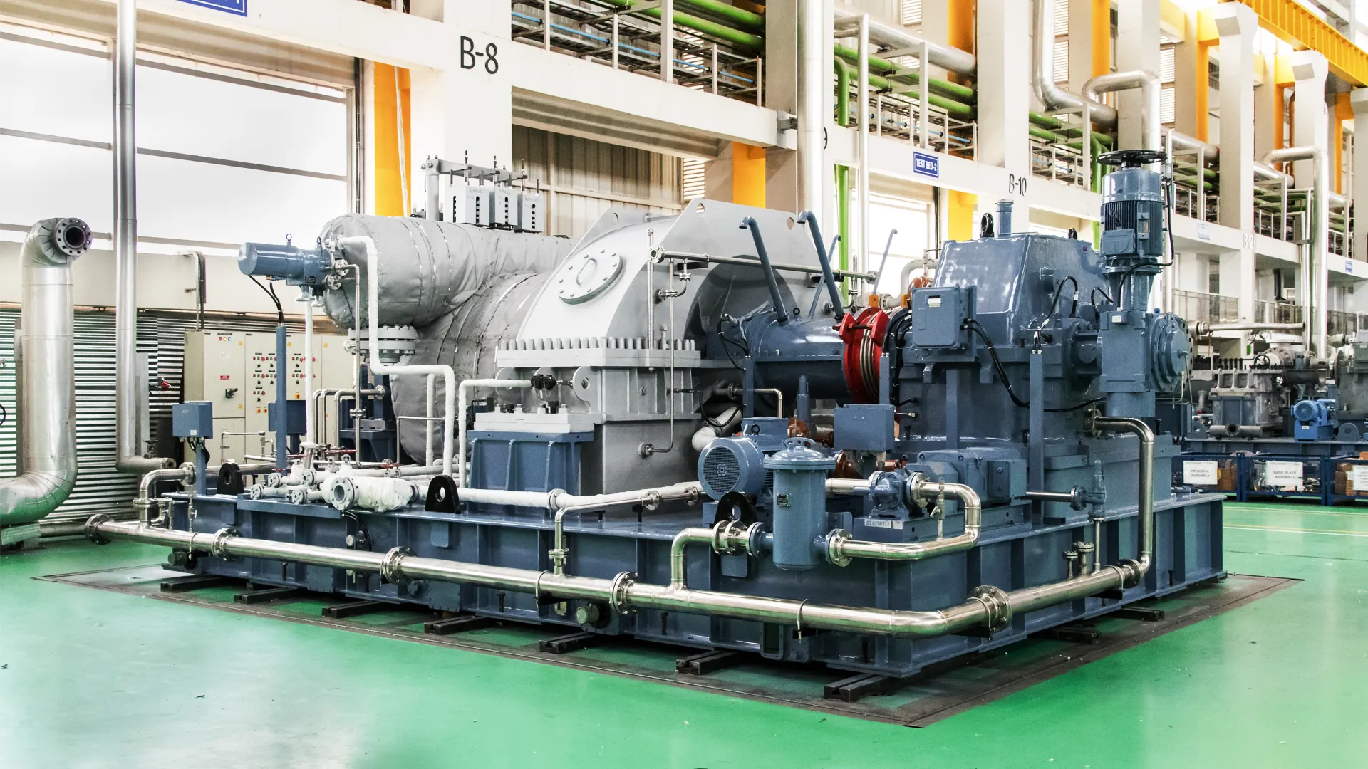
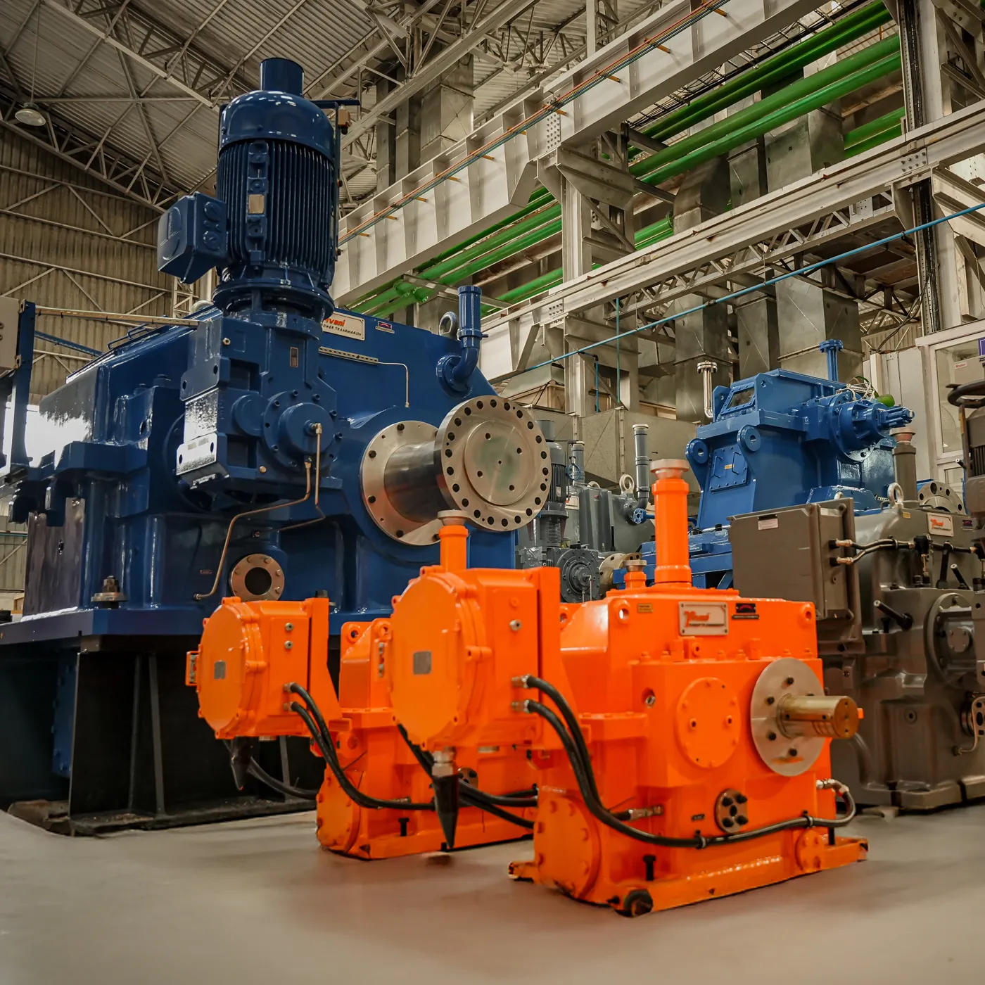
Inside the gearbox
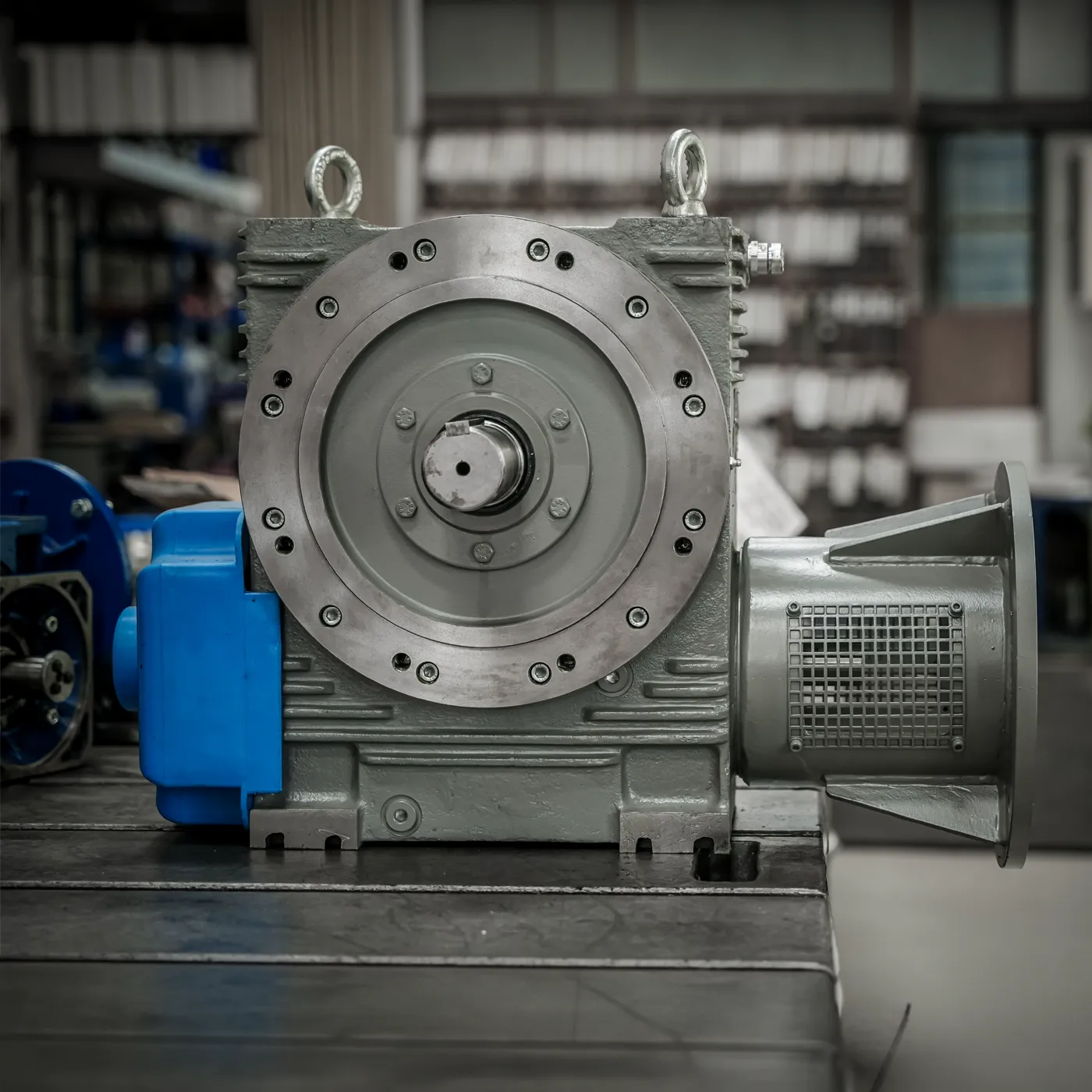
A constant-torque machine that transmits power and motion between rotating shafts without slip, delivering efficient, reliable energy transfer across a wide range of industrial applications.
Understanding gearbox engineering
Understand the basics of gearbox engineering, including how gearboxes are classified, how tooth corrections work and what makes high-speed designs reliable.
Chapter 01
Classification of gearboxes
Every industrial gearbox is defined across three key dimensions: its operating speed range, the number of gear stages and the orientation of its input and output shafts.
A Based on speed range
Gearboxes are classified depending on their operating pitch line velocity or rotational speed.
- High-speed gearboxes Speed > 4,500 RPM or > 35 m/s
- Designed for precision applications requiring high rotational speeds, such as turbines and compressors.
- Low-speed gearboxes Speed < 4,500 RPM or < 35 m/s
- Suitable for high-torque applications such as mills, conveyors and heavy-duty processing equipment.
B Based on number of stages
The number of gear stages determines the speed reduction ratio and torque multiplication.
- Single-stage gearboxes
- Used where moderate speed reduction is required with a simple design.
- Multi-stage gearboxes
- Employed for large speed reductions and higher torque transmission, offering improved efficiency and load distribution.
C Based on shaft orientation
Gearboxes are also categorised by the relative position of input and output shafts.
- Horizontal offset
- Vertical offset (staggered)
- Vertical axis
- Horizontal input, vertical output
- Vertical input, horizontal output
This flexibility allows gearboxes to be tailored to specific layout and installation requirements.
Chapter 02
Gear tooth corrections
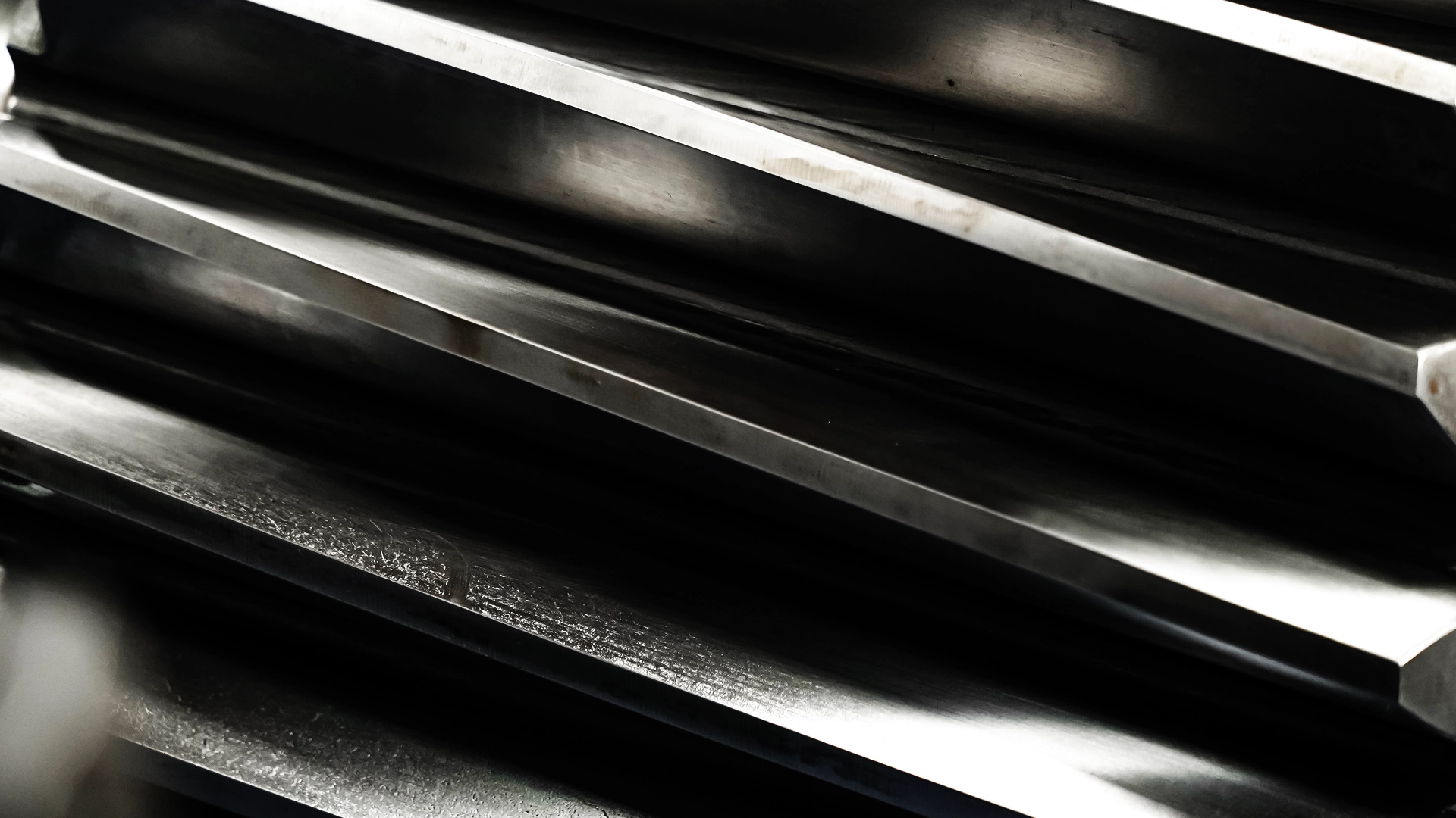
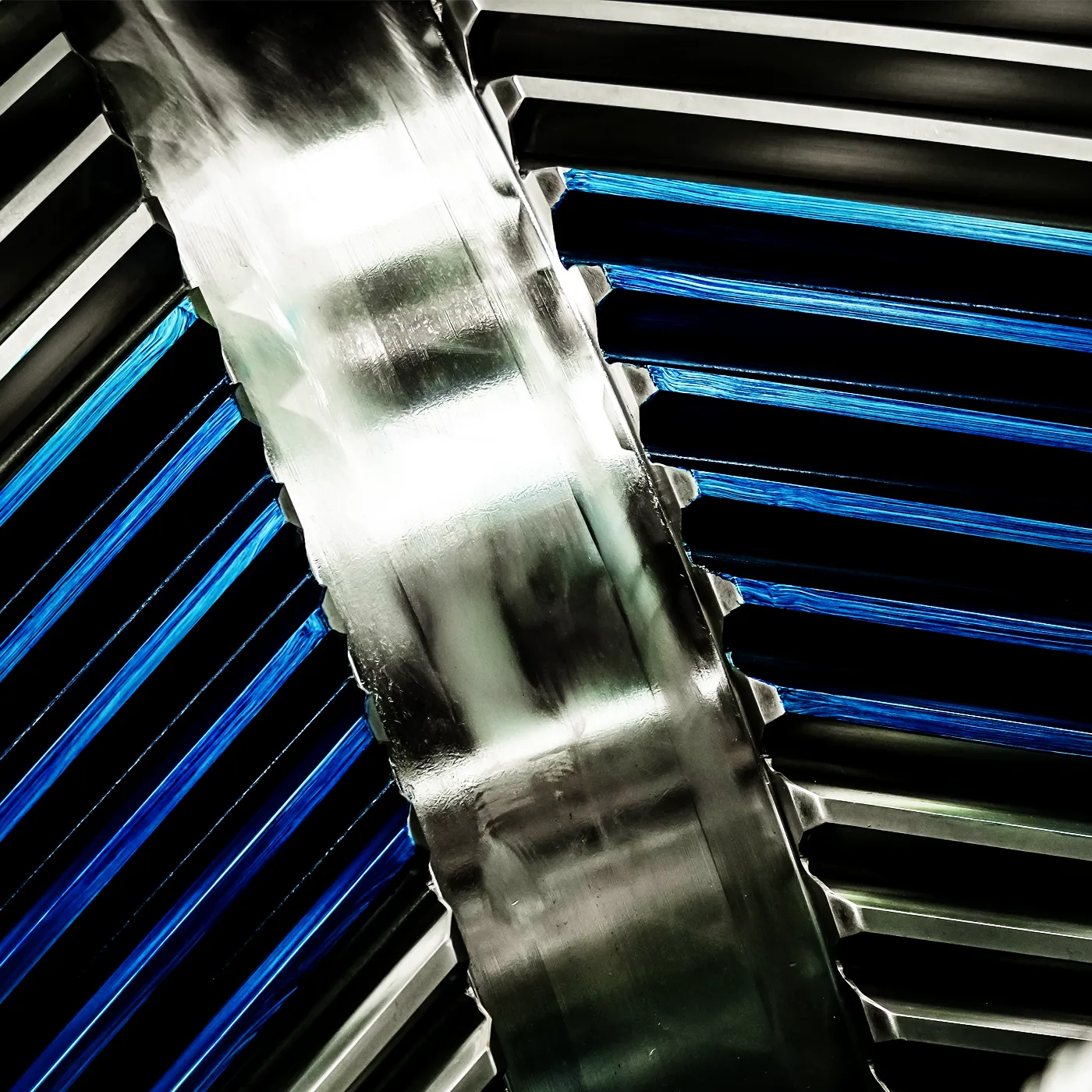
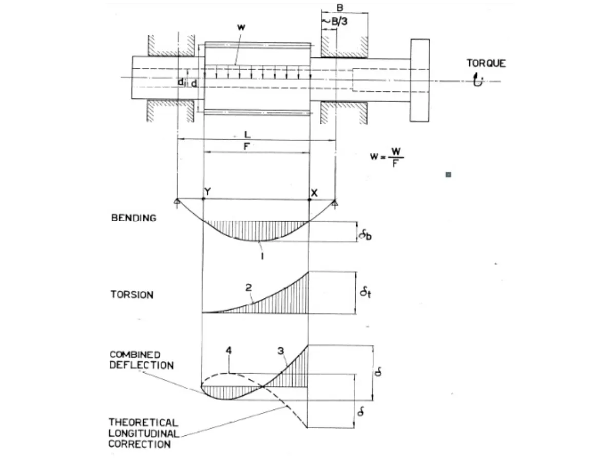
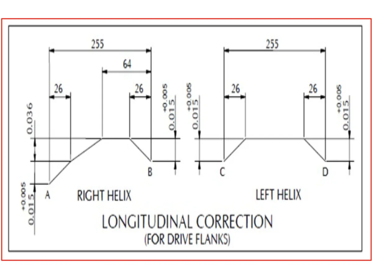
Precision in gear performance is not achieved by design alone, but through deliberate geometric refinement. Lead and profile corrections are critical micro-adjustments applied to gear geometry, ensuring optimal load distribution, smooth meshing and reliable operation under real-world conditions. Together, these modifications enhance durability, efficiency and noise performance.
A Lead corrections
Applied along the face width of the gear to improve load distribution and enable compact designs. Key considerations include:
- Lateral deflection compensation
- Addresses shaft bending under load.
- Torsional deflection compensation
- Ensures proper contact despite twisting forces.
- Thermal deformation compensation
- Accounts for expansion due to temperature variations.
These corrections help achieve uniform load distribution across the gear face, minimising stress concentrations and improving service life.
B Profile corrections
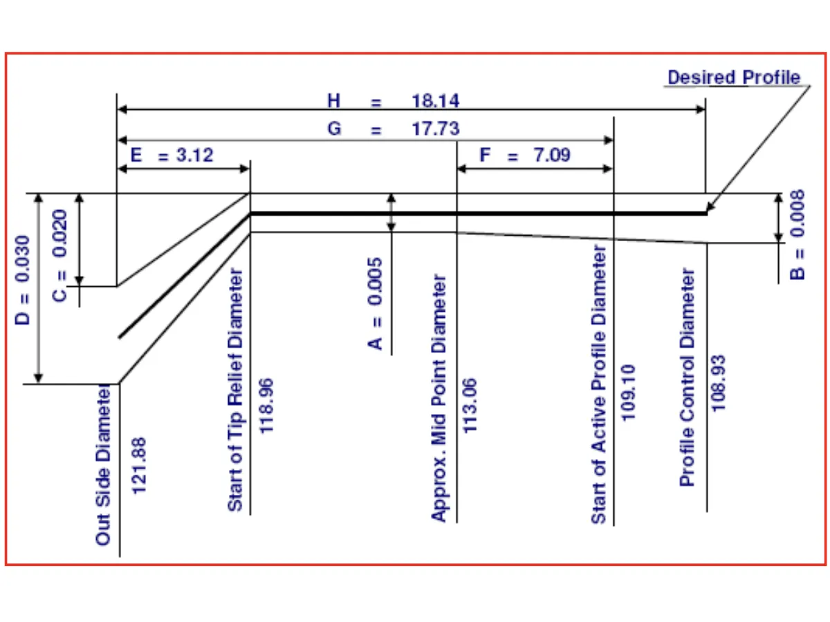
Applied along the tooth profile to enhance gear meshing characteristics and reduce operational noise. Types include:
- Tip relief (tip correction)
- Prevents interference at the start and end of meshing.
- Root relief (root correction)
- Reduces stress concentration and improves smooth engagement.
These modifications result in:
- Reduced noise and vibration
- Improved transmission efficiency
- Enhanced reliability under high-speed conditions
Chapter 03
Engineering of high-speed gearboxes
High-speed gearbox performance is governed by a combination of material integrity, precision engineering and dynamic system behaviour. From material selection and bearing design to rotor dynamics, lubrication and aerodynamic considerations, each element plays a critical role in ensuring stability, efficiency and reliability.
A Material quality & precision design
- Material cleanliness
- High-quality, inclusion-free materials enhance fatigue strength, durability and reliability of critical rotating components.
- Hunting tooth combination
- Gear tooth combinations are designed to ensure uniform wear distribution, minimising localised stress and extending gear life.
B Bearing design & selection
Bearing systems are carefully engineered considering:
- Surface velocity
- Radial and axial loads
- System stiffness requirements
Proper selection ensures stable rotor performance, reduced vibration and extended bearing life under high-speed conditions.
C Rotor dynamics
A detailed rotor dynamic analysis is essential for safe and reliable operation:
- Critical speed margin
- Rotors are designed so that critical speeds sit at least 20% away from operating speeds, avoiding resonance.
- Bearing stiffness & damping
- Optimised to control vibration levels and ensure dynamic stability across the operating range.
D Gear lubrication & thermal management
- Efficient lubrication systems
- Ensure reduced friction, wear protection and smooth power transmission.
- Cooling efficiency
- Designed for uniform temperature distribution, preventing hotspots and maintaining dimensional stability.
E Centrifugal force considerations
At high rotational speeds, centrifugal forces significantly influence gear behaviour.
- Backlash optimisation
- Proper backlash values are maintained to ensure smooth meshing and accommodate thermal and dynamic effects.
- Shrink fit design
- Accurate interference fits are used to ensure secure component assembly under high centrifugal loads.
F Aerodynamic losses (windage effects)
High-speed rotation induces air resistance, leading to energy losses and heat generation.
Designs are optimised to minimise windage losses and improve efficiency.
G System dynamics & diagnostics
Integration of gearbox behaviour with the overall system enables effective troubleshooting, root cause analysis and predictive maintenance.
Key takeaways
Industrial gearbox performance is defined by its classification across speed, stages and shaft orientation. Long-term reliability in high-speed applications is achieved through precise micro-geometry corrections and integrated engineering disciplines. Other factors that contribute are materials and bearings, dynamics and lubrication, as well as diagnostics, which ensure efficient and stable operation.